Fig 1: Graphical Representation of AIR-SYNTH
Background
Conventional carbon capture happens at a very high temperature or at a very high pressure. Electrochemical based carbon capture utilization systems can perform carbon and utilization both at a room temperature and pressure which allows for rapid modularity and scalability. During our time in developing this technology stack, we realized that some of the biggest problems and breakthroughs are required in the field of catalyst design.
What if we could accelerate the catalyst development through a unique implementation of open source hardware?
Prototype Summary
The Air-Synth prototype consists of two main components:
- Zero Gap Electrolyser Design
- Copper based Heterogeneous Catalyst
In order to utilize and convert CO2 to other chemicals, we have had two changes to the conventional PEM based electrolyser design. We went ahead with a zero gap electrolyser design. A zero gap electrolyser design reduces the size of the PEM cell while keeping the size of the membrane the same, while making the entire system modular and stackable. We also want to be able to convert this carbon utilization system to a carbon capture and utilization system. A zero gap electrolyser essentially just has a small membrane between the anode and cathode of the PEM cell. This allows the membrane to be exposed directly to the ambient air and start capturing the CO2 from the atmosphere.
Current Status
There are still some variable parameters to be worked out in terms of the carbon capture system, but as a first step we will only be focusing on converting CO2 to useful chemicals. The first one being CO, in the coming months we will be doing more tests where we try to convert CO2 to Ethanol and Ethylene. This would require a modification of the catalyst at atomic levels that we have currently used for the conversion of CO2 to CO. Here are some of the results we have obtained in our lab over the past few months:
Electrochemical conversion of CO2 to CO
- Operating conditions: Closed Continuous flow CO2 electrolyzer
- Catalyst used: Rare earth elements i.e Cu/Co/Cs/Fe and their combination thereof
- Power Supply: Variable Power Supply
- Active Surface Area: 5 cm2
- Voltage applied: 3.2 V
- Current Applied: 500mA or 100mA/cm2
- Stability of Catalyst: 500 mA ± 15mA for 120 hours or 100 ±3 mA/cm2 for 120 hours
- Faradaic Efficiency: Yet to be checked
- Conversion Product: CO (Carbon Monoxide)
- Analysis Method: Gas chromatography
- GC Method:
Injection volume: 1 µL
Carrier Gas: Helium
Carrier gas flow: 22 mL/min.
Temperature: 120 °C
Detector: TCD
Column: Shin Carbon ST
Synthesis of Catalyst
We are using the general method to synthesize the Copper/carbon catalyst
using the reported method for metallic copper catalyst elsewhere. The general process consists of dispersion of Vulcan-72 carbon in the ethanol for 1 hours to ensure the proper slurry formation at room temperature. Now added copper nitrate (40% Cu on carbon) to the slurry and stirred the solution for another 1 hour. Reduce the above slurry with sodium borohydride (NaBH4) (molar ratio 5 Cu/NaBH4). After complete addition, stirrer the suspension for next 30 minutes for complete reduction, filter the suspension and wash three times with distilled water. We dry this solid in the preheated oven 80°C overnight.
Preparation or membrane electrode assembly (MEA):


- Cathode catalyst loading: 3 mg/ cm2
- Anode catalyst loading: 3 mg/ cm2
Assembling of Electrolyzer
The following components are required:
- Electrolyzer with exposed surface are 1 cm2
- Membrane electrode assembly
The assembled electrolyzer is subjected to activation prior to use for experimentation. First moist the membrane with de-ionized water (MilliQ 18 MΩ) for 2 hours using a peristaltic pump. Now check the resistivity of the prepared MEA using Electrochemical Impedance Spectroscopy (EIS) with Potentiostat. First applied 1.2 volt and gradually increased it to 2.2 volt with the duration of 2 hours. Now the electrolyzer is ready for the experimentation.
Electrolyzer experimentation general conditions:
- Voltage applied: 3.2V
- Current applied: 1 A
- Air humidity: 60-70%
- CO2 Concentration: 650-700 ppm
- Exposure of anode: Open to ambient atmosphere
- Exposure to cathode: Open to ambient atmosphere
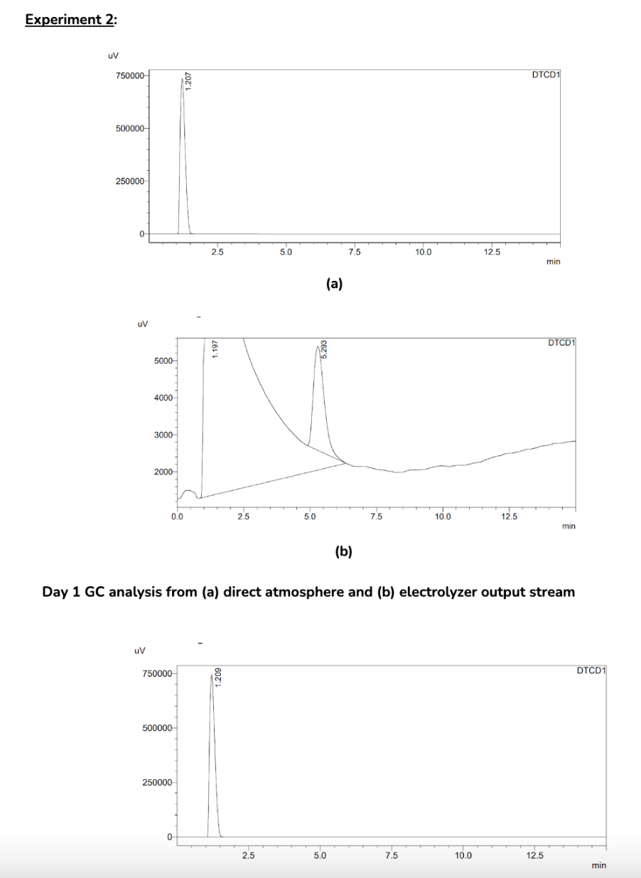
Gas Chromatography Results
The GC analysis was carried out on Shimadzu GC 2014 equipped with a thermal
conductivity detector (TCD) and ShinCarbon ST column. Helium is used as a carrier gas. The peaks at 1.19-1.2 show the presence of CO2 gas and 5.2-5.3 show the presence of CO gas. The results of different experiments with direct atmosphere gas analysis are given here: